Selected Results of experiments from the lab scale
plant
The first experiments were used for investigating different FT-catalysts, gas
cleaning methods and parameter variations. After variation of several parameters the conditions could be found to have stable
operation of the FT-synthesis without any deactivation.
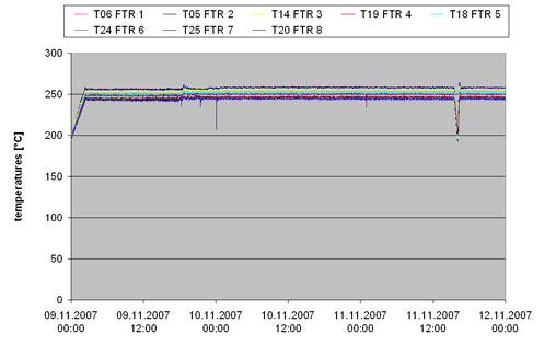
Typical temperature
distribution over the FT reactor is shown in the
following figure:
The FT-liquids produced
during operation are collected in the liquid
separators. Also in the FT reactor inside there is a change of the
hydrocarbons. The waxes used for starting are replaced
with the time by the long chain hydrocarbons produced by the FT reactions.
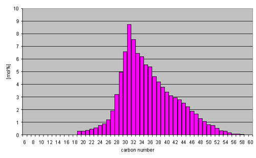
In the following figure the
distribution of hydrocarbons in the reactor is given:
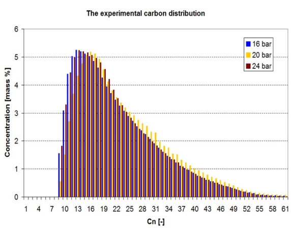
In the following figure the
distribution of hydrocarbons collected in the offgas
treatment is given:
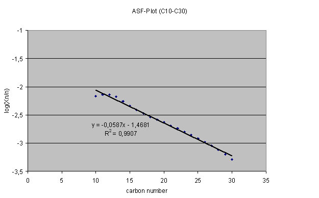
To determine the chain
growth probability the mathematical equation of the stepwise chain growth
concept according to Anderson, Flory, Schulz was used.
![]()
Wn mass fraction of species with
carbon number n
n carbon number
a chain growth probability
In the following figure the
logarithms of (Wn /n) is displayed
against the carbon number. For the plot the sum of the gas analyses, simulated
distillation of the condensed product and the simulated distillation results
from the slurry in the reactor are used. The abnormal behavior
of the plot at the low carbon numbers can be a reason that the condensation of
the product in Güssing is not complete or the gas analyses are not sufficient.
For the compounds with a carbon number from C10 to C30 an a of typical 0.9 can be
determined.
Analysis of the Diesel fraction
The fraction from the raw
FT product with a boiling range from 180-320°C was used as
Diesel and analysed by the Institute of Petroleum Processing in Poland.
Here only the results of the Cobalt based catalyst are shown:
|
Properties |
Unit |
EN 590:2004 |
World Wide Fuel Charter, category 4 |
Method applied |
Results of
FT Diesel |
Results of
HPFT Diesel |
||
|
|
|
min |
max |
min |
max |
|
||
|
Cetane number |
- |
51,0 |
- |
55 |
- |
EN ISO 5165 |
75-85 |
65-80 |
|
Density at 15 o C |
kg/m3 |
820 |
845 |
820 |
840 |
EN ISO 12185 |
770-790 |
770-780 |
|
Polycyclic aromatic hydrocarbons |
%(m/m) |
- |
11 |
- |
2,0 |
EN 12916 |
< 1 |
n.a. |
|
Total aromatics content |
%(m/m) |
- |
- |
- |
15 |
EN 12916 |
< 1 |
n.a. |
|
Sulphur content |
mg/kg |
- |
50 |
- |
sulphur free (5) |
EN ISO 20884 |
< 5 |
n.a. |
|
Flash point |
o C |
>55 |
- |
>55 |
- |
EN 2719 |
87 to
91 |
80 |
|
Carbon residue |
%(m/m) |
- |
0,30 |
- |
0,20 |
EN ISO 10370 |
< 0,03 |
n.a. |
|
Ash content |
%(m/m) |
- |
0,01 |
- |
0,01 |
EN ISO 6245 |
< 0,0015 |
n.a. |
|
Water content |
mg/kg |
- |
200 |
- |
200 |
EN ISO 12937 |
200 to
300 |
n.a. |
|
Total contamination |
mg/kg |
- |
24 |
- |
10 |
EN 12662 |
2 to
4 |
n.a. |
|
Copper strip corrosion (3h at 50 °C) |
rating |
class 1 |
|
class 1 |
|
EN ISO 2160 |
class 1 a |
class 1 a |
|
Oxidation stability |
g/m3 |
- |
25 |
- |
25 |
EN ISO 12205 |
< 5 |
n.a. |
|
Lubricity, corrected wear
scar diameter |
m m |
- |
460 |
- |
400 |
ISO 12156 |
340 to
360 |
n.a. |
|
Viscosity at 40oC |
mm2/s |
2,00 |
4,50 |
2,00 |
4,00 |
EN ISO 3104 |
2.3 to
2.5 |
2.0 to
2.2 |
|
Oxidation stability |
g/m3 |
- |
25 |
- |
25 |
EN ISO 12205 |
< 12 |
n.a. |
|
Cold Filter Plugging
Point, (CFPP) |
o C |
- |
-20 |
- |
-20 |
EN 116 |
-5 to
0 |
-50 to
-60 |
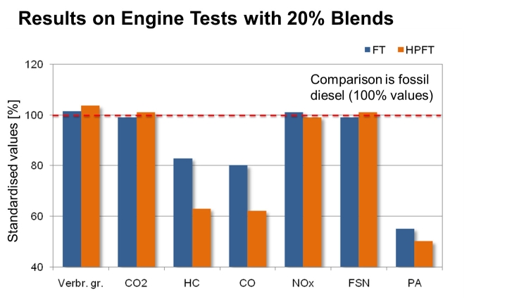
Both direct FT Diesel,
without any further treatment, but also diesel from hydroprocessing was
produced and anaylsed. The direct FT diesel consists
mainly of paraffins and has therefore a excellent Cetane
number, but poor cold behaviour. the HPFT diesel from
hydroprocessing has a high share of iso-paraffins and
and excellent cold behaviour and still a very good Cetane number of about 70. Both diesel fractions were used for blending with fossil diesel and tested in diesel
engines. As well known the FT diesel improves the properties of fossil
diesel and emissions are reduced,as
shown in the figure below.
Conclusion and Future work
As a
result of
current concerns about both crude oil prices and CO2 -accumulation in the
atmosphere, biofuels play a major role in tomorrow's energy supply. Synthetic
biofuels that can be produced from biomass via
gasification and subsequent catalytic conversion of the synthesis gas compounds
CO and H2 are one promising option to meet the ambitious goals set by the
European legislation.
While typically
only the synfuel is regarded as the desired product
and co-products such as electricity and district heat are of negligible
interest, in this concept a different approach is introduced. In polygeneration plants that purposively sacrifice some synfuel yield to the advantage of power production, a high
degree of flexibility is obtained that allows to design
the product mix to the specific needs of the market or of other production
facilities. The latter may be especially valuable for the wood processing
industry, as synergies with a complementary “energy centre” can be achieved.
Furthermore, the use of low temperature heat for district heating
which is possible in the small scale of up to 100 MW fuel power not only
adds to the viability of the process, but significantly improves the overall
efficiency and thus maximizes the amount of CO2 -savings.
Not only did the results of
this work prove the energetic advantage of such trigeneration
facilities, but equally promising break-even points
were attained. Thus, the risk of the implementation of the technologies in a
larger scale is reduced, as not only diversification
applies, but also dependence on the yet developing synfuel
technology is abated.
The next step will be a
pilot plant in the scale of 1 barrel / day, where the project will start in
beginning of April 2015.